For any diagram to draw, different constructs are required. These constructs carry certain meaning and together make the whole diagram meaningful. Requirement Tree Diagram also has various constructs that may be included as needed. This section describes the constructs of Requirements Tree Diagram in detail.
Requirement
Requirement is a behavior expected by application at given conditions. Goal of application can be split into various features or requirements. Requirements are distinct pieces of functionality for a system or a component. Being a Requirement Tree Diagram and main purpose of this diagram is to capture requirements, Requirement is a basic entity used in this diagram.
We can show a requirement as a rectangle vertically split into two compartments. Right compartment specifies the name of the requirement. Left compartment is for Requirement ID and is optional. Figure 1 shows a typical Requirement.

Figure 1: Typical Requirement

Each requirement has certain properties. Requirements accept certain input which is then processed as per the business logic to achieve the desired output of the requirement. Thus each Requirement has three distinct properties: Input, Processing Logic and Output. These properties are well-described in Section Properties of Requirement.
Actors
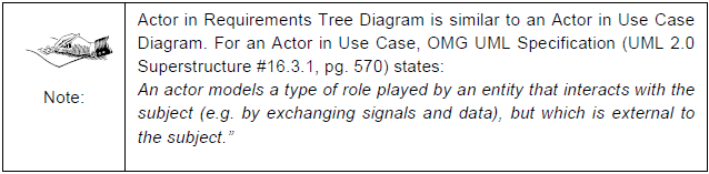
There could be certain entities, external to the requirement, interested in the requirement. Such interested entity can be called as an Actor. Actor might be interested in the requirement from the point of view of invoking the requirement, or providing certain input to the requirement or even getting certain input from the requirement. In all such cases, actors are always external to the requirement and are interacting with the requirement.
An actor specifies a role played by the external entity that interacts with the requirement. An actor may be a human user or externally visible subsystem or device interested in the requirement. It could be a big mistake if one assumes that an actor can only be a human being. External systems or elements like Timers, Actuators, and Sensors can well be assumed as Actors.
Actors can be represented in diagram by a stick-man figure. It’s mandatory to have a name for an actor.

Figure 2: Various Actors involved in ATM Application
Association between Actors and Requirements
As we have seen, actor is an external entity to the requirement interested in the requirement. Association between actor and requirement indicates that the actor is interested in or involved in the specific requirement. E.g. Association between actor “ATM Customer” and requirement “Withdraw Money” indicates that “ATM Customer” is involved in “Withdraw Money”. Association between an actor and a requirement will always be a binary Association.
A huge system may have lots of requirements and many actors. It is not necessary that every actor is interested in every requirement. Rather this cannot be the case at any given moment. One requirement may have many actors associated with it. At the same time, one actor may be interested in many requirements, though not all. In either case, it is very essential to clearly describe the association between actors and requirements.
Association between an actor and a requirement can be shown by a solid line with an optional arrow head at one end. Direction of arrow head indicates the direction of initial invocation of the relationship.


Figure 3: An Example of Association between an Actor and Requirement (Multiple ways of presentation)
Generalization of Actors
Similar to classes in Class Diagram and use cases in Use Case Diagram, actors can also be generalized. Actor generalization is typically used to pull out common role/features from several actors. There could be a possibility where certain actors (which are also having some commonalities) are involved in common requirement and at the same time individually involved in other requirements. Showing all such relations between actors and requirements with association lines may make the diagram clumsy. However by generalizing the actors, the clumsiness of diagram can be reduced drastically making the diagram simple to understand.
Actor generalization can be shown using a solid line with a closed empty arrow pointing from specialized actor to the generalized actor. Most of the times, generalized actor is abstract in nature and represents the group, all the specialized actors belong to. Abstract actors are displayed with their names in italics to distinguish them from concrete actors.
As shown in Figure 4, “Customer” and “Sales Agent” are the Actors involved in a purchase scenario. Both the actors are associated with “Place Order”, “Verify Order” and “Payment” functionality. In addition to that, “Sales Agent” is also associated with “Calculate Commission”. Drawing all above-said associations, as shown in Figure 4, makes the diagram difficult to understand. However, using Actors Generalization, as shown in Figure 5, we can keep the diagram simple. Here in Figure 5, “Purchaser” is extracted as a generic, abstract actor from “Customer” and “Sales Agent” and is associated with the functionalities with which “Customer” and “Sales Agent” are commonly associated. Association between “Sales Agent” and “Calculate Commission” is shown separately. This improves the clarity of the diagram.

Figure 4: Library Management System with Actors and Requirements

Figure 5: Library Management System Example with Actors Generalization
Relationship between Requirements
Like relationship between requirements and actors, there could be some relationship that may exist between requirements themselves. Rather we can say that system cannot have any requirement in isolation. Each requirement must have some kind of relationship with one or other classifier which can be an actor or another requirement.
A Requirement can be associated with another requirement/s. Identifying such relationship between requirements not only helps in understanding the system better but also provides a systematic approach in capturing the requirements in full. Based on behavior and expected feature, association between requirements can be classified as follows:
- Generalization
- Composition
- Pre-Condition
- Includes Relationship
- Extends Relationship
Generalization
Generalization/Specialization (a.k.a. Inheritance) is a very common concept in OOPS and is a very useful relationship that we apply on requirements. By applying generalization relationship we indicate that the specific requirement is also an indirect instance of a generic requirement and inherits all the features (and associations too) of the generic requirement.
If we are arriving at more generic form of requirement from a specific requirement/s then the process would be called as Generalization. In contrast, if we are arriving at more specific form of requirement from a generic requirement then it would be called as Specialization. Generalization is often used to pull out commonality between different requirements. In contrast, specialization is used to pull out specific requirement from generic one so that it can be concentrated independently.
A generalization relationship conveys that the target of the relationship is a general, or less specific, version of the source classifier (Requirements here). A requirement may be specialized by another requirement/s by adding or redefining features. Associations, properties of generic requirement are by default applicable to the specific requirement and to deviate from them, the same has to be explicitly captured for specific requirement. Specific requirement even inherits the expected inputs, processing logic and desired output specified for the generic requirement. Inheriting inputs and outputs is well-described in Section 4 Properties of Requirement.

Generalization is usually read as “… is a …” starting from the more specific requirement and reading towards the generic requirement.
Generalization can be shown using a solid line with closed empty arrow pointing from the specific requirement to the generic one.

Figure 6: Example of Generalization of Requirement.
In generalization relationship, most of the times, the generic requirement is an abstract one which is not complete by itself. If the generic requirement is an abstract requirement, we may put its name in italics to distinguish it from concrete requirements. E.g. in the example given below, “Print” is inherited or specialized by two requirements viz. “Print on Paper” and “Print in File”. Since only “Print” is not clarifying the target on which printing should be performed, “Print” is an abstract Requirement and so given with its name in italics.

Figure 7: Example of an Abstract Requirement.
Composition
We saw that generalization is “…. is a …” relationship between requirements. E.g. “Printing on Paper” is a “Print” requirement in its generalized form. However all the requirements don’t follow “…. is a …” relationship. There is always a possibility that one requirement/feature may be composed of many of sub-requirements. Relationship between such requirements would be a kind of “…. has a ….” relationship rather than “…. is a …” relationship. E.g. in shares trading system, there may be a base requirement “Shares Trading”, which is further composed of various sub-requirements like “”Buy Shares” and “Sell Shares”. We can say that “Shares Trading” has “Buy Shares” and “Sell Shares” as sub-requirements. Here we are establishing a Composition relationship between these requirements.
A Composition relationship can be shown using a filled diamond shape next to the owning (whole) requirement and a solid line pointing to the owned (part) requirement.
Composition is usually read as “…has a…” starting from whole requirement to part requirement. E.g. “Shares Trading” has (a) “Buy Shares” and “Sell Shares” as subrequirements.

Figure 8: Example of Composition relationship between Requirements
Composition represents a very strong relationship between requirements, to the point of containment. Composition is used to capture a whole-part relationship. E.g. in “Shares Trading” example given above, “Buy Shares” requirement cannot exist without “Shares Trading” requirement/feature. If we remove “Shares Trading” feature from the system, then it makes no sense to have “Buy Shares” requirement. In other words, “Buy Shares” doesn’t have a lifespan beyond the lifespan of “Shares Trading”. Here “Shares Trading” completely owns “Buy Shares” requirement. Thus we have a Composition relationship between these two requirements.

Aggregation is similar to Composition but with a difference that the binding between two entities is not as strong as Composition. Thus aggregated entity may have its life span beyond the life span of aggregating entity.
In case of requirements, Composition relationship is more common than Aggregation. Moreover it would be a very complicated job in making decision whether the relationship between requirements is either Composition or Aggregation. Again there is no necessity of adding such complexities while capturing the requirements. So here in Requirements Tree Diagram, both relationships viz. Composition and Aggregation are captured under “Composition” as a common heading. (Since Composition is more common, it is logical to give its name to this relationship).
Pre-Condition
It’s a quite common scenario where execution of requirements cannot start unless some other requirement is satisfactorily completed. In other words, to execute a requirement a pre-condition of satisfactory completion of some other requirement should met. E.g. in Internet banking, unless successful Login is done, other features of the system cannot be accessed at all. Thus successful Login is a Pre-Condition for all other features of the system. Such relationship between requirements can be captured using “Pre-Condition” predicate.
Pre-Condition can be shown using a dashed line, with an open arrow pointing from the dependent requirement to the requirement acting as a pre-condition. Label the line with the keyword "<<Pre-Condition>>".

Figure 9: Example of Pre-Condition relationship between Requirements
It is possible that dependent requirement may have sub-requirements (Composition) which further have included and extended requirements. (“Includes” and “Extended” relationships are explained later in this article) Applying pre-condition to a base requirement in such relations automatically applies the same pre-condition on all the sub-requirements.
E.g. Figure 10 shows a part of internet banking system with various requirements. “Print Statement” is an abstract base requirement for concrete requirements “Print Statement on Screen” and “Print Statement on Paper”. “Funds Transfer facility” is another requirement in the system which has “Money Transfer” and “Update Account” as sub-requirements. We know that print statement as well as funds transfer features cannot be executed without successful login. Thus successful login acts as a pre-condition for all these requirements. However there is no need to show separate pre-condition relationship for every requirement. As shown in the diagram, pre-condition relationship is shown between “Login” and “Print Statement” as well as “Login” and “Funds Transfer Facility” requirements. By applying pre-condition on base requirements (“Print Statement” and “Funds Transfer Facility” in this case), all the derived requirements (“Print Statement on Screen” and “Print Statement on Paper”) and sub-requirements (“Money Transfer” and “Update Account”) are automatically covered with the same pre-condition i.e. successful login.

Figure 10: Applying Pre-Condition on Base Requirements
Includes Relationship
Some requirements demand step by step execution. Putting such steps of requirement into separate requirement not only make the base requirement simple to understand, but also provides facility to share the common steps in various requirements. We may factor out common functionality from several requirements by creating a shared, included requirement.
Factoring out common repetitive patterns (sequences) in different requirements is similar to a function call. This helps avoiding redundancy that gets introduced when the same behavior is repeated at multiple places. Repeating the behavior at multiple places may also leads to inconsistencies when the behavior is changed. Using “Includes” relationship, such inconsistency can be avoided.
Typically the base requirement in “Includes” relationship is not complete on its own. The included functionality is not considered optional; it is factored out simply to allow for reuse in other requirements.
Execution of base requirement cannot be complete without execution of all included requirements. Again since included requirements are more like steps to be executed for base requirement, the sequence with which they are executed is very important.
Requirement inclusion can be shown using a dashed line, with an open arrow pointing from the base requirement to the included requirement. Label the line with the keyword “<<Includes>>”. The sequence number with which the included requirement should be executed, must be provided on “Includes” relationship line. This number can be provided immediately after “<<Includes>>” label of the line or anywhere on the line where it will clarify the sequence number of the requirement without any ambiguity.

Figure 11: “Includes” Relationship with Sequence Number of Execution

Figure 12: Factoring out Common Functionality from Several Requirements using “Includes” Relationship
Difference between Composition and Includes Relationship
As now we have seen “Composition” and “Includes” Relationship between requirements, the next question arises, “What is the difference between Composition and Includes”? Theoretically, both the relationships look alike and so it’s a difficult task to differentiate between them. However there is a way to separate out “Composition” from “Includes” relationship.
Composition relationship provides sub-requirements of a base requirement. Composition indicates that the base requirement has so and so sub-requirements. These subrequirements are executed one at a time. We can say that user is interested in these subrequirements one at a time. These sub-requirements are not necessarily common function from several requirements but they are features of the system. Composition requirements are complete in themselves. In Requirements Tree Diagram, Composition relationship finds place mainly at upper area of diagram where features of the system are introduced.
In contrast, included requirements are more like steps of the base requirement to be executed in sequence to complete the execution of base Requirement. Included requirements may be common functionality from several requirements factored out for reusability. Included requirement may not be complete on its own. In Requirements Tree Diagram, “Includes” relationship can be mainly observed at lower level of diagram where steps of requirements are captured.
Extends Relationship
This relationship allows plugging in additional functionality to a base requirement if specific conditions are met. Unlike “Includes” relationship, the base requirement is a complete requirement on its own. The extended requirement is typically smaller in scope and represents additional functionality, which may not be useful outside the context of the base requirement.
Extends relationship can be used when we have a requirement which is similar to another requirement but does a bit more. Extensions are used instead of modeling every feature by a single requirement or having complex requirements covering all variations. Extended requirement means “This Requirement is similar to that Requirement with the exception of …” Listing the extension separately makes the things easier to understand.
Extended requirement can be shown using a dashed line, with an open arrow pointing from the extended requirement to the base requirement. Label the line with the keyword “<<Extends>>”.
E.g. in Books Library System, there will be a requirement of lending books to the customers. This requirement will have sub-requirements “Issue Books” and “Return Books to Library”. “Return Books to Library” is complete in itself provided customer returns the book in time. However this Requirement can be extended by “Overdue Books Return” if customer returns the books after specified time period, in which case he may be charged with overdue fine as per rules.

Figure 13: Example of Extended Relationship between Requirements
Extended requirement may use same inputs as that of base requirement. It is also possible for extended requirement to generate the same output as that of base requirement. However processing of extended requirement is somewhat different than base requirement making it a candidate for extension. If no input or output is specified for extended requirement then we can assume that it has same input and output as that of base requirement. However If base requirement and extended requirement both are having different input and output then input and output assigned to extended requirement is only valid for extended requirement. Reuse of input and output in case of extended relationship is described in Section 4 Properties of Requirement.
System Boundaries
Generally Requirements are constrained by the functionality of a particular subject. Anything not realized by the subject is considered outside the system boundary of the subject. This technique is very useful in determining the scope and assignment of responsibilities when designing a system, subsystem or component.
We may represent system boundaries using a simple rectangle, with the name of the system at the top left corner of the rectangle.
Identifying any particular requirement for system doesn’t necessarily mean that it has to be implemented immediately. Many times a product is released periodically and for each release a set of requirements is implemented. Although it is not mandatory to show such requirements separately, grouping them within separate boundaries definitely help in segregating them as per release. E.g., as shown in Figure 1, the system has 3 releases and requirements to be implemented in each release are clearly identified and put in separate boundary.
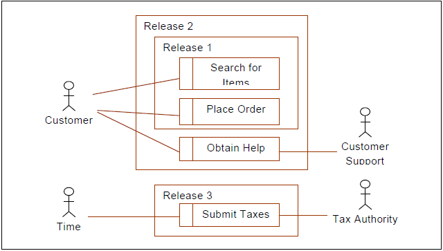
Figure 14: Example of System Boundary
It’s optional to use system boundaries, but usage of system boundaries simplifies the task of identifying the Requirements in scope. System boundary is a very useful construct. It is very flexible and can be used to group the requirements as needed. Sometimes a set of requirements have dependency (Pre-Condition) on another requirement. E.g. most of the features of internet banking are not available prior to the successful Login. The diagram becomes inept by separately showing pre-condition of all such features on Login. Rather we may put these features in a system boundary.

Figure 15: Usage of System Boundary to group the requirements having common precondition.
Packages
Packages are UML constructs that enable you to organize model elements into groups. Packages are depicted as file folders. Packages can be used in Requirements Tree Diagram when diagram becomes unwieldy, which generally implies it cannot be printed on a single page, to organize a large diagram into smaller ones.
Each package has a name that scopes each element in the package. E.g. if we have a Requirement named “Withdraw Money” in a package named “Monetary Transactions” the fully qualified name for the Requirement is “Monetary Transactions:: Withdraw Money”. However Requirements in the same package can refer to each other without qualifying their names.
We may show a package using a rectangle with a tab attached to the top left.

Figure 16: A Simple Package
A package can contain any constructs of Requirements Tree Diagram including another package itself. We may show elements contained with a package in two different ways. First, we can show the elements contained within the package by drawing them inside the large package symbol. If using this representation, write the name of the package in the tab.

Figure 17: Several Requirements contained within the Utilities and Monetary Transactions Packages.
The second representation uses a solid line pointing from the package to each contained element. Place a circle with a plus sign in it at the end nearest the package to indicate containment. If using this representation, name of the package should be shown in the large rectangle rather than in the tab. This notation allows showing more detail of the packaged elements.

Figure 18: Requirements owned by Utilities Package, shown outside of the Package

For simplicity, it’s not necessary to show all the elements contained within a package; if no elements are shown, no assumptions can be made about what the package contains.
Introducing packages in Requirements Tree Diagram is optional and can be used when Requirements are complex and the diagram is becoming too big to understand as well as to capture on one page.
Classifiers other than “Requirement”
Requirement is one kind of classifier having utmost importance in Requirements Tree Diagram. The system may have many other classifiers apart from Requirements. Users may optionally show such classifiers on Requirements Tree Diagram and associate them with Requirements or group of Requirements. Associating such classifiers with Requirements simplify the understanding of the system.

Classifiers other than Requirement can be shown as a rectangular box with name of the classifier within it. These classifiers can be associated with Requirements using a dotted line without any arrow heads.

Figure 19: Example of ChequeBook Classifier connected with ChequeBook related Features.
Connectors
Requirements Tree Diagram can be very big and complex in nature for a very large system. User is free to capture the requirements up to any extreme level. Size of Requirements Tree Diagram increases heavily with every additional requirement and with more and more details captured for a requirement. Capturing all such details in one page may not be possible at all. Even sometimes it is better to split the diagram for simplicity. Connectors are very useful constructs to maintain continuity of such dismantled diagrams.
A connector is added at the location where a diagram is to be dismantled. Putting connector at that location indicates that the rest part of the diagram below this location is captured elsewhere. Later on, on another page we may continue the diagram with the connector as if we have the requirement, connected to the connector in original diagram, at the place of that connector.
Connectors have no impact on actual requirements. They are purely used for splitting the diagram for simplicity.
Connectors are drawn as a circle with the name of connector within it. If the name of connector is big, it can be put outside the circle. Connectors are connected with requirement with a solid line. Since connectors have no impact on requirements, we may give any unique name to connectors.

Figure 20: Example of Connector
No comments:
Post a Comment